Heatsink Design
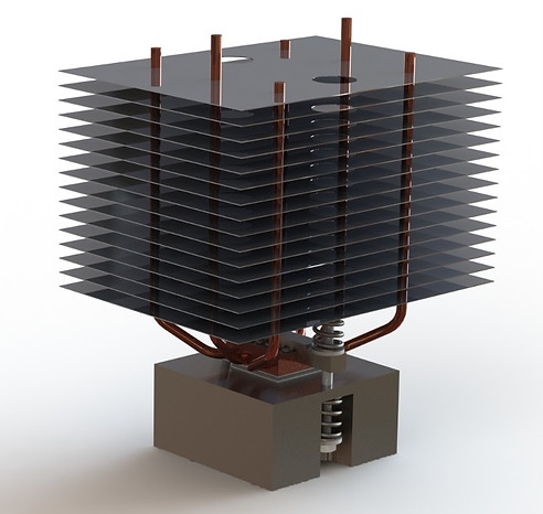
This year for my culminating senior project, I and three classmates have been tasked with designing a heatsink for operation with a thermoelectric generator (TEG). This yearlong project is sponsored by the Gas Technology Institute, and has provided numerous opportunities to practice ANSYS® thermal simulations and machining operations. Our current design including our testing base is pictured to the left
This senior project has taught me to coordinate my time with my team and how best to collaborate to efficiently meet deadlines. It has also exposed me to number of design tools such as failure mode and effects analysis that can help me ensure my designs truly meet my stakeholder's needs.

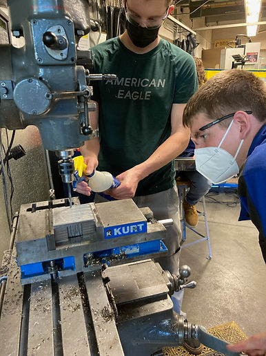
The hands on manufacturing experience from this project has reinforced a concept my SolidWorks professor would preach: somebody is going to have to build your complicated part! For example, we wanted a good surface finish on our copper base to reduce thermal contact resistance, but copper is especially soft, so chips can easily mar the surface. We solved this issue with generous use of coolant and slower passes, but the valuable lesson remained: recognize the limitations of manufacturing and costly time to achieve precise GD&T.
Another example is the complicated three dimensional bends of our heat pipes. A CNC tube bender would make short work of these shapes, but creating these by hand required complicated procedures and multiple sets of hands to accurately determine and mark the locations and orientations of bends.
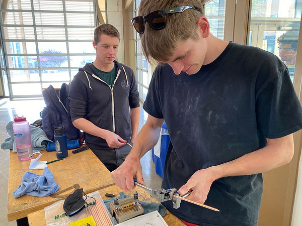
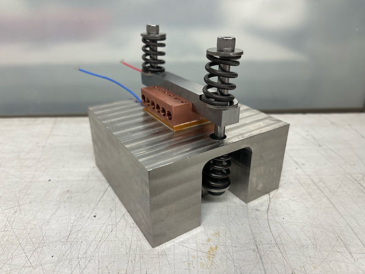
Earlier in the manufacturing process we attempted a bend with a cheap tube bender that badly crimped our heat pipes and produced non constant bend radii. The Swagelok® pictured here allowed us to accurately produce our bends and fit our heat pipes through our wooden fin jigs, seen above.

To justify our design choices and run trade studies on various heatsink components such as fin spacing or base geometry, we used ANSYS®. This taught me valuable lessons about validating computer simulations, as results are only as good as the assumptions you make.
In order to achieve appropriate material contact for brazing the fins to the heat pipes, slight flaring of the holes in the fins was required. This presented a whole new challenge in manufacturing: How to flare the holes without warping the fins?


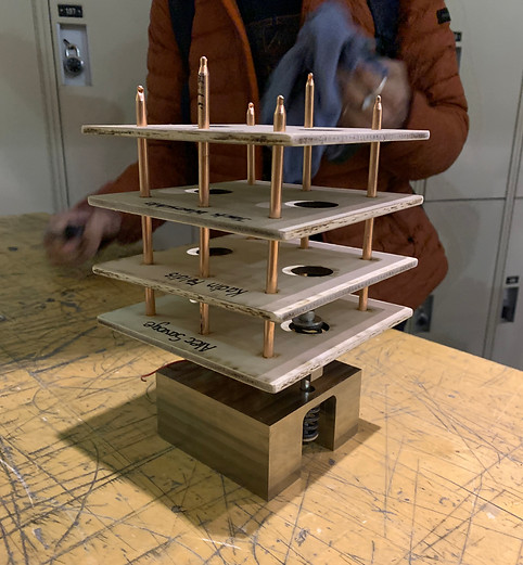
I designed the fin bending jig show above and to the left. Dowel pins are press fit into the top plate, and slide into the lower plate for easy orientation. Steel bushings are press fit into the aluminum base to reduce wear on the jig as each hole of the fins is aligned and then punched to deflect the material while the rest of the jig supports the fin and prevents bending. This provided an opportunity to practice interference and clearance hole sizing.

Overall, this project has expanded my skillset greatly and pushed me to learn new skills on a weekly basis, whether its a software program like ANSYS® or a tool such as a Swagelok®. It is the embodiment of Cal Poly's motto: Learn By Doing.